
 1941
1941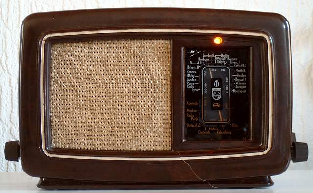 1941
1941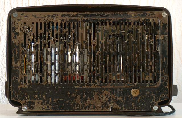 1941
1941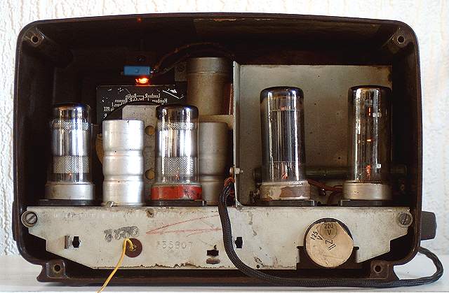 1941
1941 |
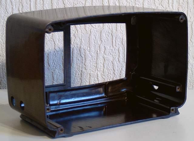
Cabinet | 60% |
|
Reception AM | 70% |
|
Sound Quality AM | 50% |
 |
P.U. Entrance: | Yes |
| |
Tape Recorder Entrance: | No |
| |
Extra Loudspeaker Output: | No |
| |
Loudness: | No |
| |
Treble Control: | No |
| |
Bass Control: | No |
| |
Tone Register Switches: | No |
| |
AM Bandwidth Switch or Control: | No |
| |
Tuning Indicator: | No |
| |
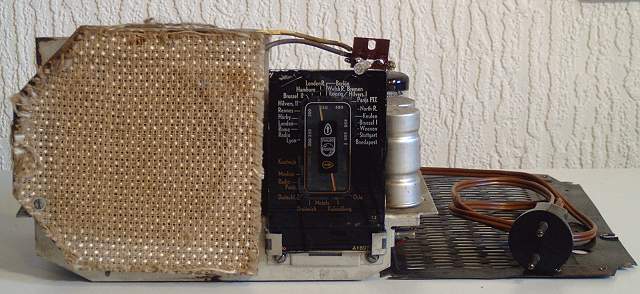
Build-in Antenna: | Yes, metal back-plate |
| |
Build in Ferrite or Window Antenna: | No |
 |
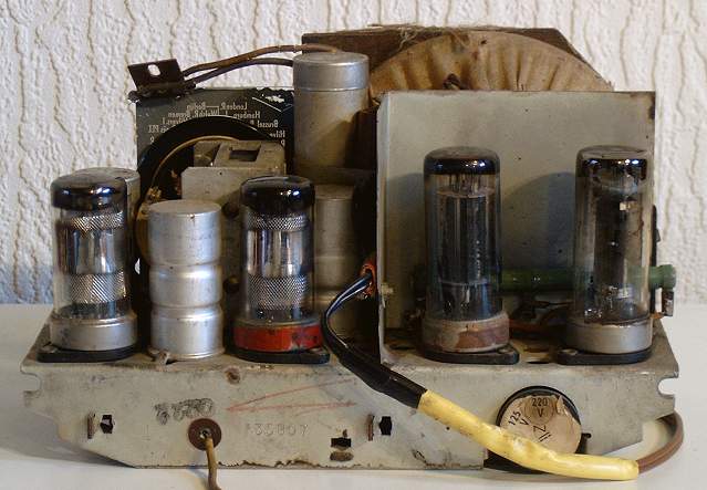
Tubes: | UCH21, UCH21, UBL21, UY21. |
|
Wave Bands: | LW, MW. |
|
Intermediate Frequency (IF): | 452 kHz |
|
Loudspeaker: | 9668 |
|
Resonance Frequency Fs: | ? |
|
Frequency Range Power Amplifier: | ? |
|
RMS Output Power at 5 Ohms: | ? |
|
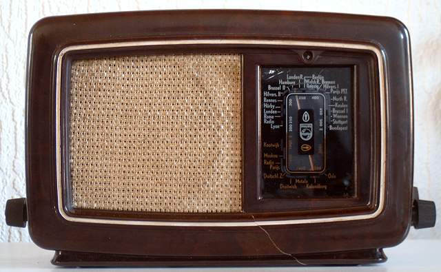
Cabinet: | Bakelite, dark brown. |
|
Dimensions: | 24.5
x 16.5 x 13 cm |
|
Mains Power Voltages: | 127, 220 Volts~ |
|
Mains Power Consumption | 42 Watts |
|
Retail Price | f 82.50 |


 Home Back
to Picture Gallery 1 Contact
Kees van Dijke
Home Back
to Picture Gallery 1 Contact
Kees van Dijke