Philips B0X19U/00L
1961
1961
1961
Condition and performance:
|
Cabinet |
60% |
|
Reception AM |
60% |
|
Sound Quality AM |
60% |
Features:
|
P.U. Entrance: |
No |
|
Tape Recorder Entrance: |
No |
|
Extra Loudspeaker Output: |
No |
|
Loudness: |
No |
|
Treble Control: |
No |
|
Bass Control: |
No |
|
Tone Register Switches: |
No |
|
AM Bandwidth Switch or Control: |
No |
|
Tuning Indicator: |
No |
|
Build-in Antenna: |
Yes, plate antenna |
|
Build in Ferrite or Window Antenna: |
No |
Technical Specifications (Partially measured):
|
Tubes: |
UCH81, UBF80, UCL82, UY89. |
|
Wave Bands: |
MW |
|
Intermediate Frequency (IF): |
452 kHz |
|
Loudspeaker: |
AD 1400/00 |
|
Resonance Frequency Fs: |
? |
|
Frequency Range Power Amplifier: |
? |
|
RMS Output Power at 3 Ohms: |
1.5 Watts |
|
Cabinet: |
Bakelite, orange painted |
|
Dimensions: |
26.2
x 13.8 x 14.2 cm
|
|
Mains Power Voltages: |
110, 127, 220 Volts~ |
|
Mains Power Consumption |
43 Watts |
|
Retail Price |
?
|
Description:
The Philips B0X17U is the same radio as the
Philips B0X15U, but the dial scale is different. It has a needle which
shifts in the horizontal direction.
The electronic circuit and performance is the same same as the Philips
B0X15U.
Repairs:
- Paper/tar capacitor C19 of 100 nF is replaced by an ERO capacitor of
100 nF 1000V.
Reason: This capacitor is exploded due to leakage.
- Ceramic capacitor C18 of 10 nF is replaced by 10 nF 630V.
Reason: Ceramic capacitor seems te be have flash-overs which results in
noise and a crackling sound.
- A 120R 5W resistor is added in series with the heater circuit.
Reason: The heater circuit is now calculated for 232V~ mains power
voltage.
- Amplifier is modified, similar as in the Philips B0X15U for more
stability and a better sound quality. See the schematic diagram below.
After these improvement, the radio plays much better. In the future, the
volume potentiometer will be decoupled from the AM detection circuit. See
the report of the Philips B0X17U
how this can be done.
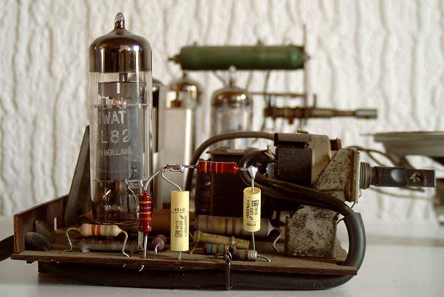
Below you see an example of the added components how to get more bass
output. The coupling capacitor C17 of 4700 pF 1000V is also renew.
Performance:
The sensitivity of this radio is just sufficient, but to receive more
distant broadcast stations, it is recommended to connect an external
antenna. A piece of wire of 2 meters is sufficient.
The sound quality in its original state is very thin and harsh. There is no
loudness circuit build in as well as no negative feedback circuit. After
adding some extra components, the sound quality has improved a lot.
Disclaimer:
This
radio is directly supplied from the mains power. The high voltage supply is directly taken from the
mains power, which means the radio chassis and components carries
the 230 Volt~ mains voltage, which is very dangerous. Before making any
repairs on the radio or playing the radio without the back plate, use a
safety transformer with separate windings. The insulation of the windings
must withstand at least 4000 Volts AC as well as a low leakage current of
0.5 mA~ or less.
Home
Back
to Picture Gallery 3
Contact
Kees van Dijke
Download
the schematic diagram
© Copyright 2015 by Kees
van Dijke