
 1959
1959 1959
1959 1959
1959 |
Cabinet: | 80% |
|
Reception AM: | 80% |
|
Reception FM: | 70% |
|
Sound Quality AM: | 50% |
|
Sound Quality FM: | 50% |
|
Sound Quality P.U.: | 50% |
 |
P.U. Entrance: | Yes |
|
Tape Recorder Entrance: | No |
|
Extra Loudspeaker Output: | No |
|
Loudness: | No |
|
Treble Control: | Yes, switchable |
|
Bass Control: | No |
|
Tone Register Switches: | No |
|
AM Bandwidth Switch or Control: | No |
|
Tuning Indicator: | No |
|
Build-in Antenna: | Yes, MW plate antenna |
|
Build in Ferrite or Window Antenna: | No |
|
Separate AM/FM tuning: | No |
|
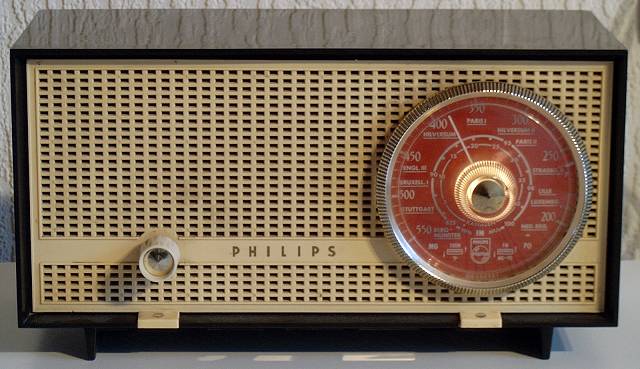
Tubes: | ECC85, ECH81, EF89, UABC80, UL84, UY85. |
|
Wave Bands: | MW, FM from 87.5 - 100 MHz |
|
Intermediate Frequencies (IF): | 452 kHz, 10.7 MHz |
|
Loudspeaker: | AD 1400 W |
|
Resonance Frequency Fs: | ? |
|
Frequency Range Power Amplifier: | ? |
|
RMS Output Power at 5 Ohms: | ? |
|
Cabinet: | Bake-lite, dark brown. |
|
Dimensions: | 29.5 x 15.5 x 14 cm |
|
Mains Power Voltages: | 110, 127, 220 Volts~ |
|
Mains Power Consumption | 45 Watts |
|
Retail Price | ? |
The UL84 shows blackened traces on the glass due to overload, but the UL84 is OK and there is no positive grid voltage.
 Home Back
to Picture Gallery 3 Contact
Kees van Dijke Download
the schematic diagram
Home Back
to Picture Gallery 3 Contact
Kees van Dijke Download
the schematic diagram