
 1956
1956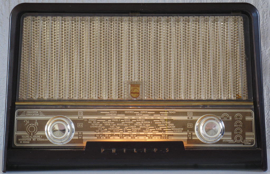 1956
1956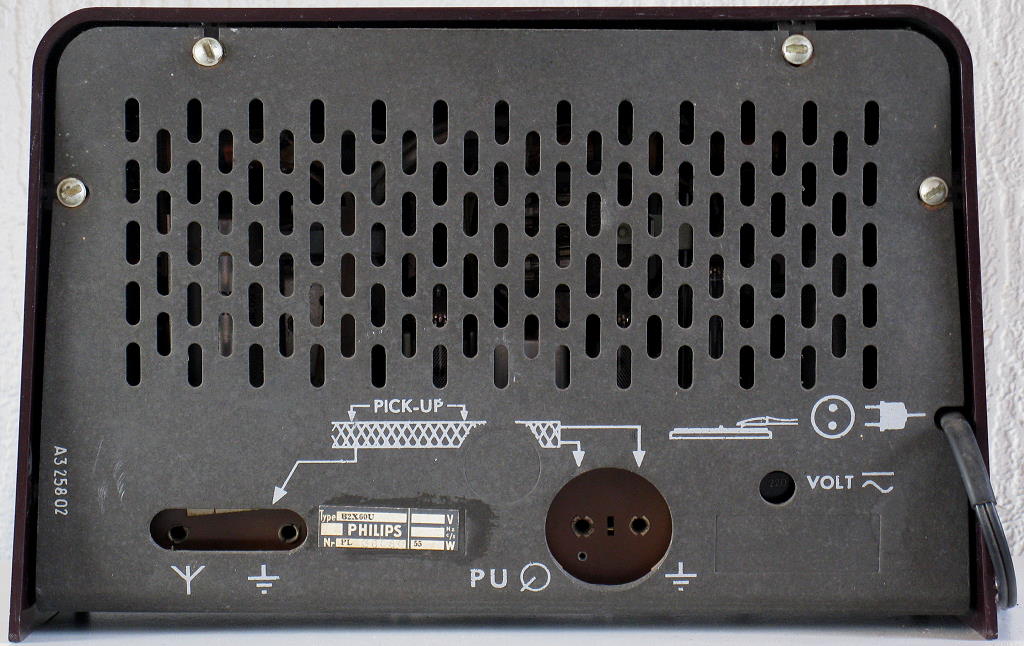 1956
1956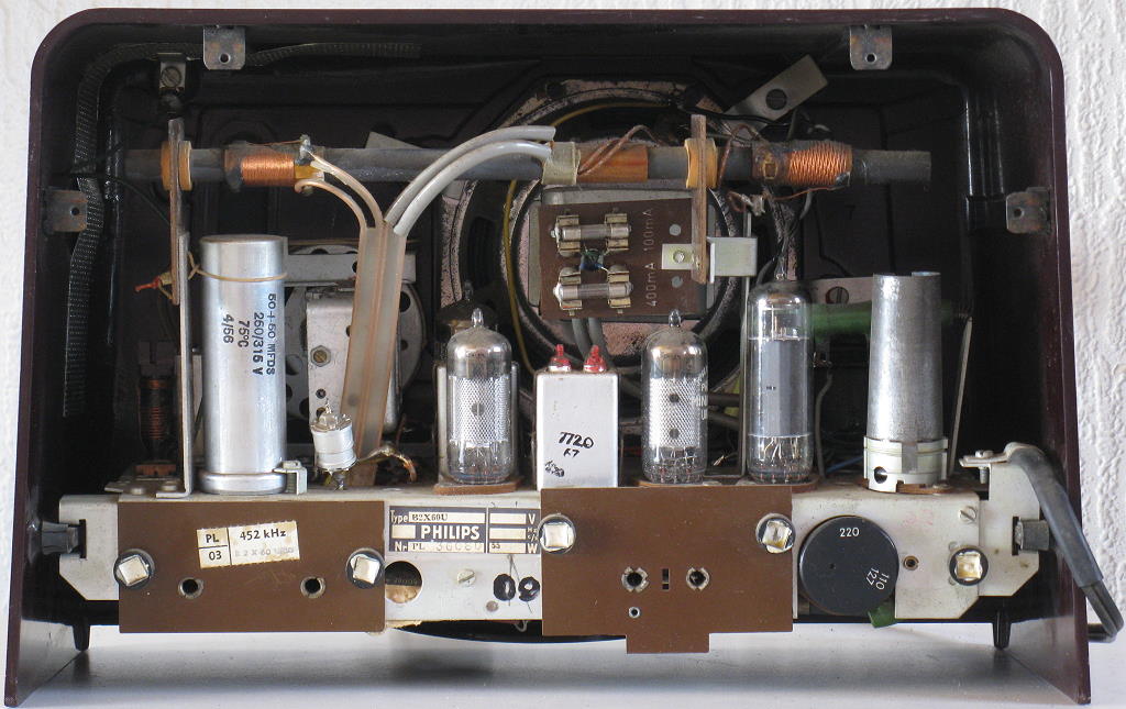 1956
1956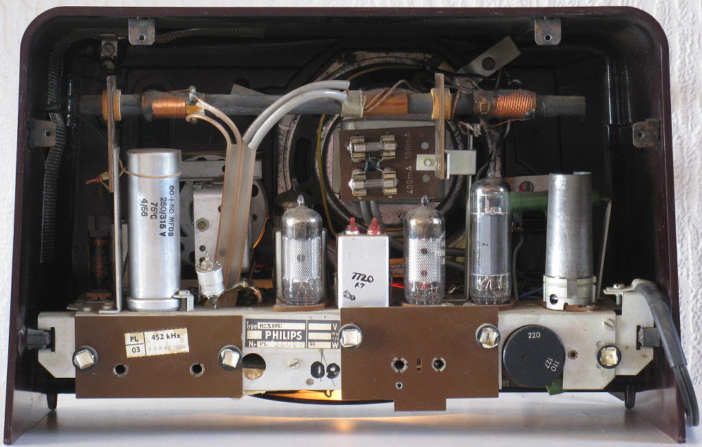 1956
1956 1956
1956 |
Cabinet: | 90% |
|
Reception AM: | 90% |
|
Sound Quality AM: | 70% |
|
Sound Quality P.U.: | ? |
 |
P.U. Entrance: | Yes |
|
Tape Recorder Entrance: | No |
|
Extra Loudspeaker Output: | No |
|
Loudness: | Yes, bass |
|
Treble Control: | Yes, switchable |
|
Bass Control: | No |
|
Tone Register Switches: | No |
|
AM Bandwidth Switch or Control: | No |
|
Tuning Indicator: | No |
|
Build-in Antenna: | Yes, SW plate antenna |
|
Build in Ferrite or Window Antenna: | Yes, MW and LW ferrite antenna |
|
Tubes: | UCH81, UF89, UBC81, UL84, UY42. |
|
Wave Bands: | LW, MW and KW from 16 - 50 meters |
|
Intermediate Frequencies (IF): | 452 kHz |
|
Loudspeaker: | AD 3500 X |
|
Resonance Frequency Fs: | ? |
|
Frequency Range Power Amplifier: | ? |
|
RMS Output Power at 5 Ohms: | ? |
|
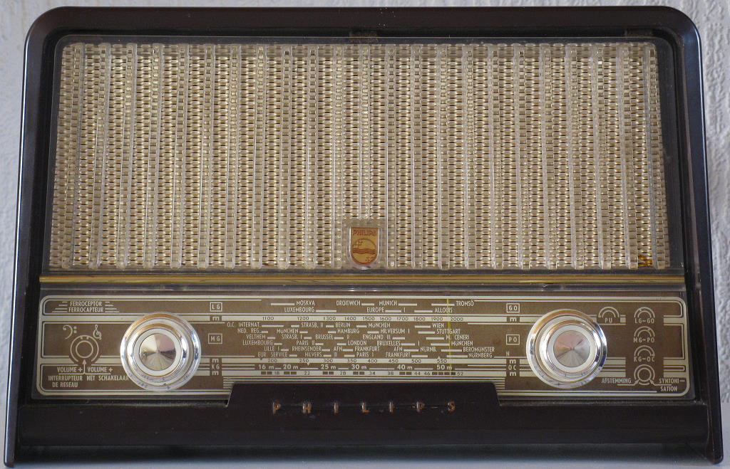
Cabinet: | Bake-lite, dark brown. |
|
Dimensions: | 32.5 x 19.5 x 18.5 cm |
|
Mains Power Voltages: | 110, 127, 220 Volts~ |
|
Mains Power Consumption | 55 Watts |
|
Retail Price | ? |
 Home Back
to Picture Gallery 3 Contact
Kees van Dijke Download
the schematic diagram
Home Back
to Picture Gallery 3 Contact
Kees van Dijke Download
the schematic diagram